In late 2016 I approached my wife, Jeannine, to see if she had any interest in incorporating synchronized wirelessly controlled lighting in her dance company. She latched onto the idea and a significant project ensued. One which required everything to be created from the ground up, including:
- Finding a tube material which would was strong enough to support the physical stress expected for a prop, while being an efficient translucent “light cover”
- Mechanical design of the tube ends and inner workings, providing an access method for recharging the batteries, while not creating shadows on the tube surface from the either the batteries or the electronics.
- Finding a power source capable of supplying 120W and enough energy for more than an hour of continuous operation
- A method for programming complex sequences and patterns
- A method for synchronizing the sequences to a series of songs, below the level of human perception
- A method for identifying each tube in a group of visually identical tubes
Seven months and four mechanical revisions later, the light tubes made their performance debut, providing a unique form of expression in LightEscapes at the Cowell Theater in San Fransisco.
Along the way three printed circuit boards, two embedded applications and a custom light sequence creation / performance controlling PC application were needed to turn the concept into a reality.
Artist and Audience Perspective
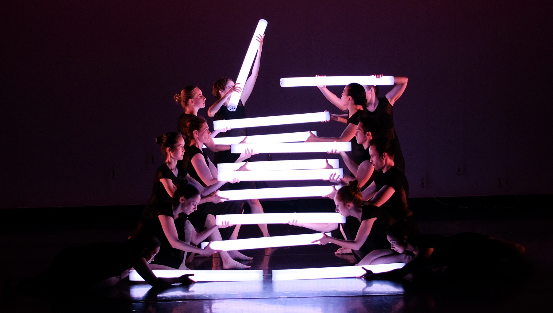
From the viewer’s perspective the light tubes are 1m (39″) long by 10cm (4″) round, translucent tubes, flat white when inactive. Each tube contains 30 rows of LED lights, each row capable of generating one of 16 million unique colors every 5ms epoch. Each tube can generate a maximum intensity of nearly 22,000 lumen, or the equivalent of more than thirteen 100 Watt incandescent bulbs. The tubes can be programmed with a sequence of colors that enable the choreographer to create localized lighting which can be both dynamic in variation and mobile. The timing of each of the tubes with respect to each other and music is synchronized will below human perception. With twelve tubes, each with their own independent color sequences, in one ~24 minute piece, there are over 100 million light transitions. Transitions can be fast enough strobe like a powerful flash or slow enough to be barely perceptible, providing a broad range of possible expressions. The following clip demonstrates a pair of light tubes representing a pair of hearts beating in unison followed by a one second fade to white and then slow bleed from top to bottom.
A short excerpt from Light(e)scapes demonstrates how the lighting enhances the visual impact of the choreography, creating a unique experience. Note the synchronization between the light flashes and music at 0:48, 0:52 and 0:56. In these pieces the majority of the lighting originates from the Light Tubes, save the occasional down light and back light.
Unfortunately, the camera’s limited dynamic range in a dark environment with matrix metering fails to capture the full fidelity of the light tubes animation. In person, the visuals are even more compelling.
System Executive Summary
Performance Scenario
Due to the volume of data per piece, the system is intended to be run in one of three scenarios:
- Performance
- Creation
- Programming
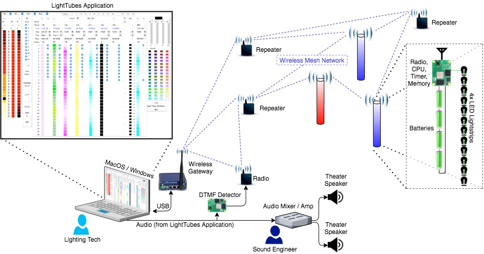
In the performance scenario, the lighting sequences have been programmed into the light tubes and audio source for each piece has been loaded on the Lighting technician’s laptop running the LightTubes application. The light tubes have been turned on and have joined the wireless mesh network 30+ minutes prior to the start of the performance and their connection status is visible to the lighting technician. Now:
- The lighting technician selects the music / light sequence for the upcoming piece
- The sound engineer mutes the audio to the theater
- On the stage manager’s signal the lighting technician plays the current sequence. The LightTubes application plays a precisely 10.000 second clip of four DTMF tones, followed by several seconds of dead audio and then the music for the piece.
- The DTMF detector converts the DTMF tones into pulses fed into the precision timing input of a mesh network radio.
- A dedicated mesh network radio records the time of the pulses against its network timer and sends a message with the timing information to the LightTubes application
- The LightTubes application calculates the network time the light sequence should start and broadcasts a message with the start time and the selected light sequence to all of the light tubes in the network. The mesh network provides spacial and temporal redundancy ensuring reliable operation regardless of the positioning of the light tubes and performers.
- The sound engineer unmutes the theater audio. The muting of the audio from on steps 2 through 7 prevent audience from hearing the DTMF tones.
- At the calculated time, the light tubes synchronously, but independently, play through the light sequences based upon their individual programming. Inside the light tubes, the CPU and radio work in tandem to maintain timing accuracy well below human perception.
- Once a tube has reached the end of a light sequence, it returns to an idle state, still in network, with the lights turned off waiting for the next light sequence queue.
This sequence is repeated for every piece incorporating light tubes in the show.
Creation Scenario
Creation of light sequences can be done with our without a connected network of light tubes. The download process for a piece to the light tubes can take several minutes, so typically the choreographer will develop “lighting phrases”, testing those on the light tubes to fine tune the lighting effects prior to connecting all of the “lighting phrases” together to form a sequence. The LightTubes application can been run on OS X and Windows. The interface can be thought of as a paint program with multiple layers, each layer being a combination of light tubes. Layers can exist in parallel in time and light tubes can transition from one layer to another. They layers are virtual, defined by the set of tubes which are enabled with up to 12 layers being active at any one time. The light sequences are built on a series of transitions, where transitions can be init, fade, swipe up, swipe down, or end. Aside from init, which sets the starting colors and end which sets the final colors all other transitions include a transition time and a duration. The transition time is the time for all LEDs to transition from their initial values to their final values and the duration is the time from the end of the last transition to the start of the next transition. The start and end of each transition have user defined colors for all 30 positions on the tube, referred to as a LightTube Palette. The following video illustrates the more common operations.
Given the chosen representation, all sequences are defined by:
- Transition Type (init, fade, swipe up, swipe down, or end)
- Transition Time
- Duration
- Starting LightTube Palette
- Ending LightTube Palette (the next transitions Starting LightTube Palette)
However the transitions are defined, each of the rows linearly changes from its starting color to its ending color. For example if a row started as blue and ended as red with a 2 second transition time, 1 second after the start of the transition the color would be a mid shade of purple. Swipe up and swipe down transitions can start or stop on any one of the 30 positions and color values for fractional time periods in the swipe movement are linearly spatially interpolated, providing a smooth transition effect regardless of the length of a transition period. The bleeding transition shown in the demonstration video above, starting at the 0:16 mark is an example of linear interpolation creating the appearance of a slow moving swipe down. The main LightTube application screen is divided as follows:
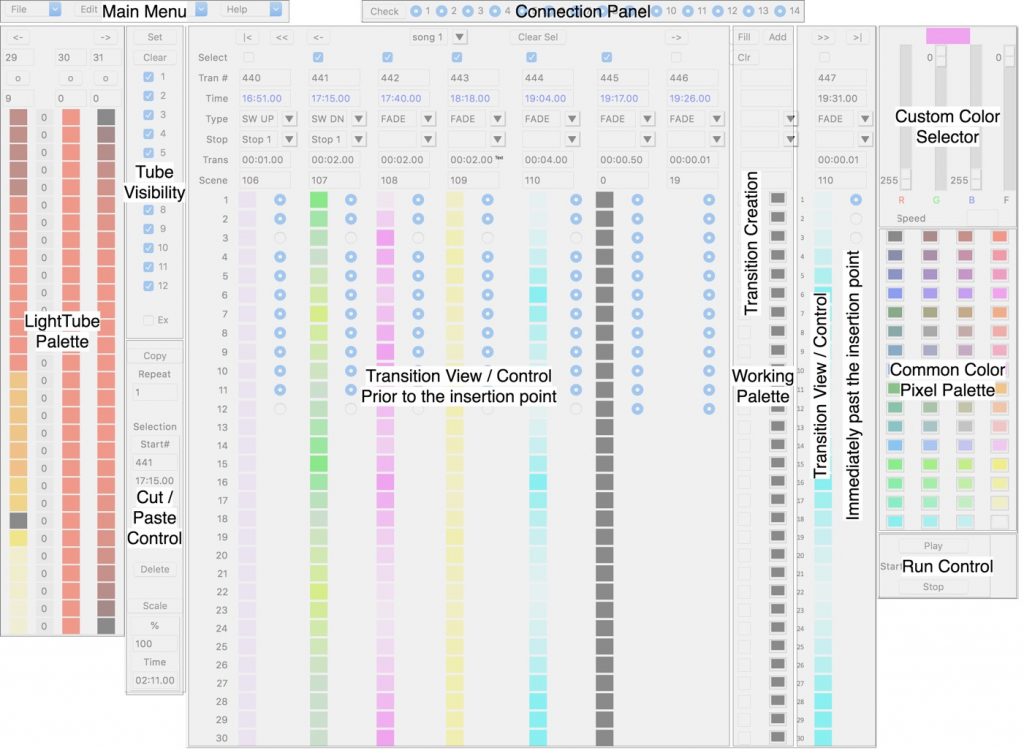
Main Menu: the main menu allows for assigning, saving, recalling and renaming of the application files in addition to providing a selection of options to download the light sequences.
Connection Panel: The connection panel provides the connection status of each of the light tubes. The check sets clears all of the status indicators and then runs an accelerated check on the status of every light tube.
LightTube Palette: A scrollable palette showing all of the palettes assigned to any of the transitions. The arrow buttons at the top can be used to navigate through the lists of palettes. The 2nd row displays the palette ID. This ID can be entered in the Scene field to select a palette from the lists of palettes. Alternatively, the buttons on the third row can select a palette. Once selected, the palette becomes the current Working Palette. In the center column of the lightTube palette to the left of the color swatches, there are numbers, predominantly zero. Those numbers represent the magnitude of pseudo random flickering assigned to the color. For values greater than zero the color values will be modulated towards black with a varying frequency and amplitude, providing a flickering effect. This effect can be useful for representing motion such as emulating the flickering light from a candle. The flicker value can be entered as the fourth component in the Custom Color Selector in the upper right hand corner or can be entered for each row to the left of the color swatches in the Working Palette.
Cut and Paste Control: Color sequences often repeat, such as the heart beat in the first 16 seconds of the demonstration video above To expedite copying and deleting of transitions the Cut and Paste Control works in conjunction with the select boxes in the Transition View / Control pane. When transitions are selected the earliest and the latest selections define the start and end of the source to be copied. The destination is the transition number, labeled “Tran #”, after the last transition number shown in the Transition View / Control pane to the immediate left of the Working Palette. The source can be replicated a number of times by entering a whole number in the repeat field and the speed can be modified by entering a percentage change in the Scale field. The duration of the resulting sequence is shown in the Time box at the bottom of the Cut and Paste Control pane.
Tube Visibility: As mentioned previously sequences can be run simultaneously on virtual layers defined by the tubes on those layers. The Tube Visibility pane allows the user to display those sequences that include any one of the selected tubes or only the specific combination of the selected tubes.
Transition Creation and Working Palette: The Working Palette represents the colors which will be assigned when the next transition is created, and resides in the Transition Creation pane. The Transition Creation pane includes the entry fields required for creating a transition and can be thought of like a cursor in a text document. To add transitions, move the Transition Creation Pane so it appears between the two transitions where the desired transition should be added and then create a transition. The changes in time will be automatically reflected in the transitions occurring after the newly inserted transition. The time entries are made in hundredths of a second and are automatically accumulated to to the end time of the previous transition. The transition number, labeled “Tran #”, is automatically assigned and modified as needed and represents the position of the transition from the start of the piece.
- “|<” Jump to start
- “<<” Jump back 10
- “<-” Jump back 1
- “->” Jump forward 1
- “>>” Jump forward 10
- “>|” Jump to end
Common Pixel Color Palette: Selecting any of the color swatches in the Common Pixel Color Palette sets the current color to the swatch color. The current color will be reflected as the current color in the Custom Color Selector and will be assigned to any row in the Working Palette selected.
Run Control: Allows the user to set the start time from the begging of a piece, start and stop the sequence on the light tubes. The application will automatically trim the audio set for a piece to match the start time and the light tubes will begin at the matching point in the sequence, such that the light tubes are synchronized to the audio.
Programming Scenario
Programming 90 minutes of content can take 20 to 30 minutes. Not shown the utility screen allows a user to assign physical tubes, identified by address to any of the 12 tubes, including allowing for duplicates.
Power On Identification
Immediately following power on each light tube will illuminate rows from the bottom of the tube for 10 seconds to indicate its assigned tube number. For numbers less than five every other row is illuminated, so that for tube #1, row 1 is illuminated, tube #2 has rows 1 and 3 illuminated and tube #4 has rows 1, 3, 5, and 7 illuminated. For tubes #5 through #9 all of the first five rows are illuminated and the rows beyond that alternate so tube #6 has rows 1, 2, 3, 4, 5 and 7 illuminated. Tube #9 would have rows 1, 2, 3, 4, 5, 7, 9, 11 & 13 illuminated. Tubes 10, 11 & 12 all have rows 1 to 5 and 7 to 11 illuminated and then alternating rows illuminated so tube #10 would have rows 1-5 and 7-11 illuminated, tube #11 would have rows 1-5, 7-11 and 13 illuminated. These patterns allow the theatre technicians to quickly identify each tube.
Design
The design files for this project have been captured here on GitHub. In this post I have subdivided the project description into the mechanical aspects of tube construction, the circuit designs and the software.
Tube Construction
The problem of tube construction centered on requirements for creating the correct light effect, while being robust and serviceable. Starting with tube selection, the intent was to have an object which was sufficiently large to be clearly visible to the audience who may be as far as 200 feet from the light tubes while being small and light enough dancers can freely move with a tube held in one hand. Commercially available options for a translucent white tube are limited. Polycarbonate tubes are available; however are more expensive and heavier than the High Density Poly Ethylene (HDPE) tubes chosen. Interestingly the HDPE tube application driving the need for a translucent tubing is for feeding of pigs where it is important to be able to see where the level of material in the tube, but important to not allow the animals to identify the tube contents as food through the tube walls as motivated pigs will chew through the tube walls to get to the food.
With the outer tube selected the next issue to resolve is providing a surface in the center of the tube to affix the LED strips, the closer to the edge of the tube, the less diffuse the light will appear. With the goal of not having any shadows on the surface of the tubes the electronics and batteries needed to be housed towards center of the tube from the LED strip surface. Clear Extruded Acrylic 1″ Square Tubing was chosen as it is light, has four surfaces for the LED strips and has sufficient interior volume to fit the batteries and electronics sitting on a 3/4″ Polyethylene Terephthalate Glycol (PETG) sleeve.
To hold the center square tubes in place end caps were constructed from two disk shaped layers of Acrylic, the 1/4″ thick inner layer and a 1/8″ outer layer as shown in the image below.
The inner layer includes several cut outs not found on the outer layer. To create the end caps, these cutting guides were printed on sticker sheets and adhered to the 1/4″ thick, 3″ diameter Acrylic disk. The cut outs and holes not found on the outer layer were made, then the disks were ground to fit the a specific matching tube. The wall thickness of the outer tubes varied from tube to tube and even around the circumference of a specific tube, so the caps needed to be sized to a specific tube. The 1/4″ end caps where then welded with Acrylic Plastic Cement, to the 1/8″ acrylic sheet, cut and sanded, with an oscillating drum sander, to match the wall thickness of a specific tube. With the end cap in place in the tube a pair of holes for the 4/40 machine screws were drilled 1/8″ from the end of the tube, centering the hold on the 1/4″ edge of the inner cap layer. After removing the caps the holes where tapped. These matching holes in the tube and the cap provided the means for attaching the end caps to the tube.
The top end cap shown above is permanently mounted to the clear extruded Acrylic 1″ square tubing which will be referred to as the inner tube in this article. Initially this bond was made with acrylic plastic cement; however, during the course of rehearsal the tubes were often dropped. While the cement bond would hold, the acrylic square tubing would crack and eventually sever into multiple pieces. The design was changed to provide a cutout in the 1/4″ cap with an additional, 1/8″ margin around the square tubing and an elastomeric sealant/adhesive was applied; however, the adhesion proved to be insufficient, leading to the use of cloth tape as an intermediate material providing sufficient bonding to the inner tube, while providing a better bonding surface for the elastomeric sealant/adhesive. This final combination has proven to be durable enough; although, due to the curing times of the elastomeric sealant/adhesive the outer HDPE tubes are used to hold the 1″ tubes in place while curing.
Both the top and bottom end caps also include a elastic straps that allow the tubes to be attached to theater rigging. the straps are constructed with tapped holes on the inside surface in the 1/4″ acrylic caps which modified hooks are screwed in. A hole just to the center of the hooks is used to feed a 4″ hair band through, providing an external elastic. The elastic, when not in use, sits near flush to the cap’s outer surface, but can be pulled up to an inch away from the surface and is strong enough to support the weight of several tubes. The bottom end cap also has three rubber feet, allowing the tubes to freely stand on a flat surface.
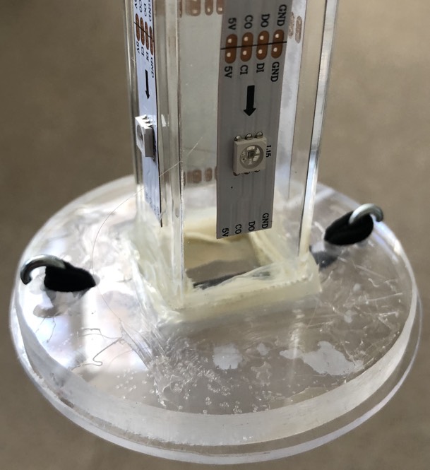
The LED strips have an adhesive backing and are connected to the electronics housed inside the inner tube via a custom designed printed circuit board which provides a reliable bus between controlling circuit and the four LED strips. The completed construction of the white PCB soldered to 0.1″ centered single row headers which in turn are soldered to the LED strips is shown in the image below. The semicircular notch in the square tube allows for the wiring from the electronics in the center of the tube reach the connector, shown on the right of the image. The zip tie was added to increase robustness of the harness out of caution.
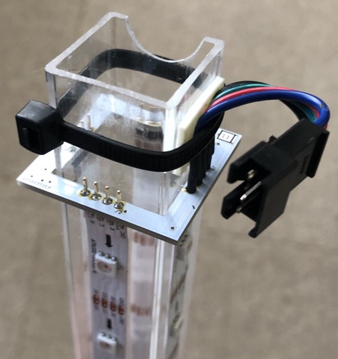
The top cap, constructed using the same techniques as the bottom. In addition the top cap includes an extra opening for a power switch, a semicircular opening for wiring egress and a pair of countersunk machine screw holes for attaching the electronics sleeve. The following image illustrates the complete construction of the bottom cap + sleeve.
The sleeve inserts into the inner tube as shown in the following image. The sleeve must be inserted so the egress point for the wires matches the semicircular cutout in the square tube. As a result the holes for mounting the bottom cap to the outer tube are not drilled and tapped until the cap / sleeve orientation is matched to the inner tube.
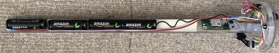
To attach the sleeve to the cap an acrylic rectangular block is welded to the end of the 3/4″ Polyethylene Terephthalate Glycol (PETG) sleeve. When cured, the end of the sleeve is carefully cut to create a consistent 90° angle. The sleeve with acrylic block is then drilled and tapped in place with the bottom cap. Prior to mounting the electronics an angular acrylic bar is welded to the sleeve near the rectangular block to form a diagonal surface for mounting the mote breakout PCB, the white PCB with the green LTP5901 PCB mounted to it in the image above. The mote breakout PCB is attached to the angular acrylic bar via adhesive backed velcro. The single pull double throw (SPDT) switch is mounted to the bottom cap via two 4-40 machine screws and simultaneously switches three of the batteries in series to supply ~3.6V to the mote breakout PCB (Radio SoC + Flash) and all four batteries in series to supply ~4.8V to the LED strips.
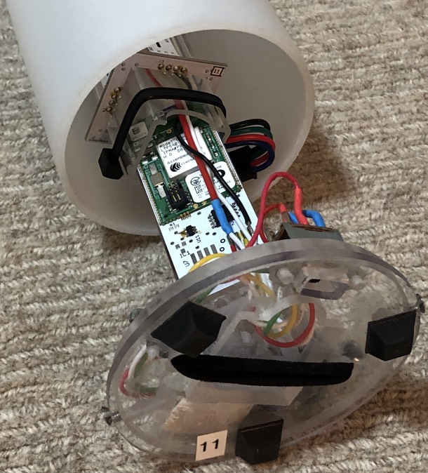
The bottom cap and sleeve includes a keyed connector for the LED strip combiner PCB. This enables the bottom cap and sleeve to be disconnected and completely removed, allowing for removal and recharging of the four AA NiMH batteries.
Circuit Design
The majority of the electronics complexity is embedded in the purchased components for the system. The access point for the network manager and the nodes used as repeaters are all part of this kit. Sadly the kit has been repriced from $500 to $3,000. The capabilities of this product are truly unique in terms of timing accuracy, power consumption and reliability. Circuit design files for all three custom PCBs for the tube design can be found here. The Bill of Materials (BoM) includes all of the components, both mechanical and electrical. The LEDStripCombiner and CapConnector PCBs exist only to provide a reliable method to wire the system. The MoteBreakout PCB connects the LTP5901’s SPI Master bus to to the serial flash and the LED strips. The LED strips are not designed for use on a shared SPI bus, so the MoteBreakout PCB design gates off the clock from LED strips when other devices, such as the flash, are being accessed.
One note the system power architecture. The design powers the radio & flash from three of the four cells in the battery stack while powering the LEDs from all four, not considered a good design practice for most solutions. However, in this use case, the typical power consumption of LED strips is on the oder of 100,000 to 1,000,000 times the power consumption of the radio and flash, so the battery to battery variance will by far swamp the effects of the asymmetrical load due to the drain from the radio and the flash. The second issue with this approach is not driving the inputs to the LED flash strips to their supply rails, which will result in leakage at those inputs; however, this leakage again will be insignificant relative to the power draw of the LEDs themselves. The signal to noise ratio on the inputs has plenty of margin and bit errors, if any have occurred, have been insignificant in their affect on the LightTube output.
Software
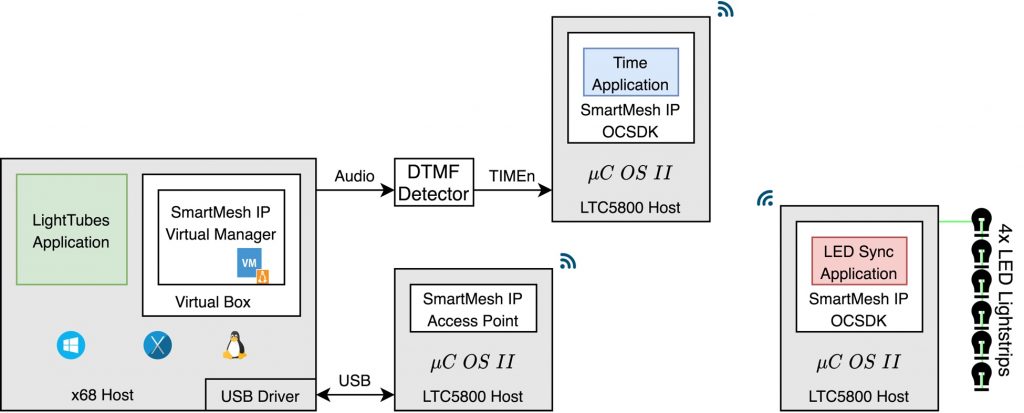
The software architecture can be subdivided by the supporting hardware instances, as shown in the following diagram. The LightTubes application (shown in green) and Network manager reside on an x86 host, nominally a laptop, running either a Windows, OS X or Linux OS. The SmartMesh IP Virtual Manager runs on a Linux VM running in Virtual Box and connects to the LightTubes application vi JSON encoded messages over HTTP. The SmartMesh IP Virtual Manager connects to the SmartMesh IP wireless mesh network via a virtual serial port over USB connecting to the SmartMesh IP Access Point application running on a LTC5800 based host. The Time Application (shown in blue), responsible for detecting the demodulated DTMF tones and synchronizing the audio timing to the network timing also runs on an LTC5800 based platform. The LED Sync Application (shown in red), responsible for translating between encoded network packets and the SPI flash interface as well as playback of lighting sequences synchronized to network time also runs on a LTC5800 based platform. All of the LTC5800 platforms share a common OS, driver and network interface layer, allowing for compact applications which have limited overhead for non-application specific tasks. The SmartMesh On Chip Software Development Kit (OCSDK), includes all of the physical layer drivers, network layer functions including reliable communication and timing management.
Timing, Synchronization and Network Performance
The timing solution provided by the SmartMesh IP software and LTC5800-IPM made a nearly impossible task manageable. The SmartMesh IP products implement a patented solution which maintains synchronization of nodes in the network to less than 2uS all while using less than 20uA of current to do so. In comparison this is between 100 and 1,000 times more accurate than the most accurate quartz watches and consuming roughly the same current while also maintaining a wireless network. In a world where wireless products are notoriously unreliable, the network stack, both in architecture and software quality, produces a solution which is extremely robust. Through the entire development, there was never a single network failure or observed packet loss. When producing a live show one expects problems; nevertheless, having the wireless network be the most reliable component in a live show is astonishing.